BY-PASS VALVES.
Another feature which plays a most important part in the successful operation
of the articulated compound locomotive, and so should be clearly understood by
the engineer, is the by-pass valves.
The purpose of these valves is to prevent the injurious effects which would
otherwise result from the pumping action of the large low pressure pistons when
the locomotive is drifting.

These valves are so designed that they automatically establish communication
between the two ends of the cylinder, when the engine is running with the
throttle closed, thus performing several important functions:
First, they prevent alternating vacuum and compression in the cylinders when
the locomotive is drifting, thus insuring the free movement of the pistons.
Second, by permitting the circulation of the free air drawn into the cylinders
through the vacuum-relief valves, they prevent this air from being overheated
by the churning of the pistons and thus destroying the lubrication, when the
locomotive is drifting down a long hill.
Third, by destroying the vacuum which, without them, would be formed by the
large piston, they prevent the smoke and gases from the smoke box being sucked
into the cylinder.
Fourth, they prevent excessive fanning of the fire from the pumping action of
the large pistons when drifting
These valves are located in chambers cast in the outside of each low pressure
cylinder. Their construction is shown in Fig. 9. There are two valves to each
cylinder. The lower view in the illustration shows the two valves U with the
heads T of the chambers in which they are located; while the upper view shows
the valves alone without the valve chamber heads.
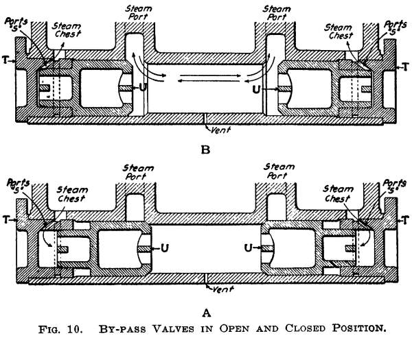
Fig. 10 illustrates the arrangement of the valves when assembled in their
chamber and their relation to the steam ports in the cylinders.
In position A of this latter figure, the valves U are in the position they
assume when the throttle is open. In this position the steam passing from the
steam chest ports through the small ports S in the head T of the valve chamber,
as indicated by the arrows, acts against the outer ends of the valves U and
keeps them against their seats, cutting off communication between the admission
ports of the cylinders.
Position B of Fig. 10 is the one the by-pass valves U automatically takes when
the throttle is closed. In that event the atmospheric pressure admitted through
the small air vent in the valve chamber forces the valves U open, closing the
steam chest ports and establishing communication between the admission ports at
either end of the cylinders. This permits circulation from one end of the
cylinder to the other when the locomotive is drifting, accomplishing the
necessary results enumerated.
It
is strongly recommended, therefore, that in drifting the reverse lever be kept
at ¾-stroke or more, since when operated in this way the locomotive will drift
freely.
As the by-pass valves perform such important duties, it is essential that they
be properly cared for and kept in good condition, to prevent them from
sticking. The engineer can tell at once if the by-pass valves are stuck open,
as, in that case, steam will blow from the small pipe projecting from under the
jacket midway between the ends of the cylinder. This pipe connects to the air
vent in the center of the chamber containing the valves.
>From the above description it will be seen that if the bypass valves stick
open it will cause a severe blow. When the locomotive is first put into service
the by-pass valves should be taken out and cleaned quite frequently to keep
them free of core sand which will undoubtedly work in. After this has been done
a few times they require only ordinary attention.
If the low pressure engines are heard to thump as if a piston, crosshead or box
were loose and the locomotive does not drift freely, the trouble probably lies
in the bypass valves being stuck closed by being gummed, and these should be
taken out and cleaned at the first opportunity.
Sticking of the by-pass valves may be caused by smoke box gases being sucked
into the cylinders by the pistons when the locomotive is drifting with the
reverse lever "hooked up." These gases would be sent circulating
through the bypass valves which are oily from the steam, and the soot may stick
to them and form a gum. This gum hardens gradually and the valves ultimately work
so hard that the comparatively light suction in the steam chest is not strong
enough to open them. On this account periodical cleaning of these valves should
be made.
The possibility of smoke and gases being sucked into the cylinders will be
minimized, if the reverse lever is kept at ¾-stroke or more when the locomotive
is drifting.
VACUUM AND RELIEF VALVES.
In
the high pressure steam chests or some other convenient place which is in
communication with the steam chests, are located vacuum valves. The function of
these valves is to admit free air into the steam chests when the locomotive is
drifting so as to avoid a vacuum and give a moderate flow of air through the
cylinders.
The low pressure cylinders are equipped with combined vacuum and relief valves
which in addition to having functions similar to the vacuum valves of the high
pressure cylinders also regulate the steam pressure in the low pressure steam
chests. These relief valves are set at 45 per cent of the boiler pressure.
As these valves relieve any excessive pressure in the low pressure cylinders,
they should be tested occasionally to see that they are correctly set.
>From the previous description of the intercepting valve it will be seen
that when the locomotive is working compound the packing rings of the high
pressure valves and pistons alone separate the boiler pressure from the
pressure in the receiver and low pressure cylinders. Consequently if there was
a blow in these packing rings, the pressure in the receiver would be increased,
causing the relief valves in the low pressure steam chests to blow off.
Therefore, if these valves rise from their seats frequently when the locomotive
is working compound, it might be due to the fact that there was a blow in
either the valves or the pistons of the high pressure cylinders, and these
should be tested.
To test for blows simply throw the emergency operating valve in the cab to the
simple position, namely, with the handle pointing to the rear. Spot the
locomotive and test the same as a simple locomotive.